...
- Topology Notification flow
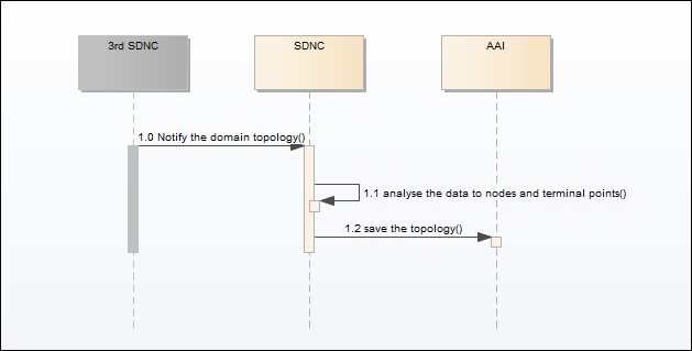
1.0 3rd SDN controller notify the single domain topology to SDNC.
1.1 SDNC analyse the data from 3rd SDN controller. Get the nodes, links, terminal points of the topology.
1.2 SDNC call A&AI to create the nodes, links terminal points to save the topology.
Note: For multi 3rd SDN controllers, there will be several topologies notified. The links across the domain topology should be discovered or created by ONAP. - Vpn Infra Service Deploy Flow


- 2.0 The user clicks the button on 0 UUI/Portal to deploy the CCVPN service, UUI/Portal will sent the deploy request to SO.create VPN Infra Service
- 2.1 SO decompose the CCVPN service template distributed by SDC.1 SO create service instance to AAI
- 2.2 SO calls A&AI to create the new service instance in inventorydecompose the service template.
- 2.3 SO calls call SDNC to create CPE configure VPN resource
- 2.4 SDNC calls A&AI call AAI to create CPE configure resource instance and attach this VPN resource instance to the service instance.
- 2.5 SO call SDNC to configure CPEactivate VPN resource
- 2.6 SDNC call 3rd SDN SOTN controller to configure CPE.
- 2.7 SO call VFC to create vCPE VNF
- 2.8 VFC create the vCPE VNF instance in A&AI.
- 2.9 SO call VFC to instantiate vCPE VNF
- 2.10 VFC call 3rd VNFM to deploy the vCPE.
- 2.11 SO call SDNC to create vCPE configure resource
- 2.12 SDNC call A&AI to create vCPE configure resource instance and attach this resource instance to the service instance.
- 2.13 SO call SDNC to configure the vCPE
- 2.14 SDNC call the 3rd SDN controller to configure the vCPE.
- 2.15 SO create the VPN network resource instance in A&AI and attach this resource instance to the service instance.
- 2.16 SO query the network access points which CPE and vCPE connects to from the inventory OSS. This access point are the terminal point of the topology in A&AI that notified by 3rd SDN controller(Refer to the flow 1).
- 2.17 SO call OOF to calculate the route between the topology terminal points of CPE and vCPE.
- 2.18 OOF query the whole topology information from A&AI.
- 2.19 OOF calculate the route for the terminal points. And return a VPN list across multi topology.
- 2.20 SO loop the VPNs to call SDNC to instantiate the VPN instance.
- 2.21 SDNC call 3rd SDN controller create vpn over the domain topology.
- 2.22 SDNC add relationship between domain topology and the VPN instance and return the VPN instance to SO.
- create SOTN VPN instance if it is needed. For EPLine/EVPLine ,this operation is not needed here. For EPLAN/EVPLAN, it is needed to create a VPN with no UNIs in the 3rd SOTN controller.
- 2.7 SDNC call AAI to create SOTN VPN Instance, the instance will be related to VPN resource instance.
- 2.8 SDNC call 3rd SD-WAN controller to create SD-WAN VPN instance. This means all the sites deployed later will be attached to the same VPN.
- 2.9 SDNC call AAI to create SD-WAN VPN instance, the instance will be related to VPN resource instance2.23 SO call A&AI to attach the VPN instance to VPN network resource instnace.
3. Service Design Flow
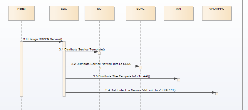
- 3.0 Design the service in SDC portal
- 3.1 SDC distribute the service information to SO
- 3.2 SDC distribute the service network information to SDNC
- 3.3 SDC distribute the service model information to AAI
- 3.4 SDC distribute the service VNF information to VFC/APPC.
...