...
*Each Requirement should be tracked by its own User Story in JIRA
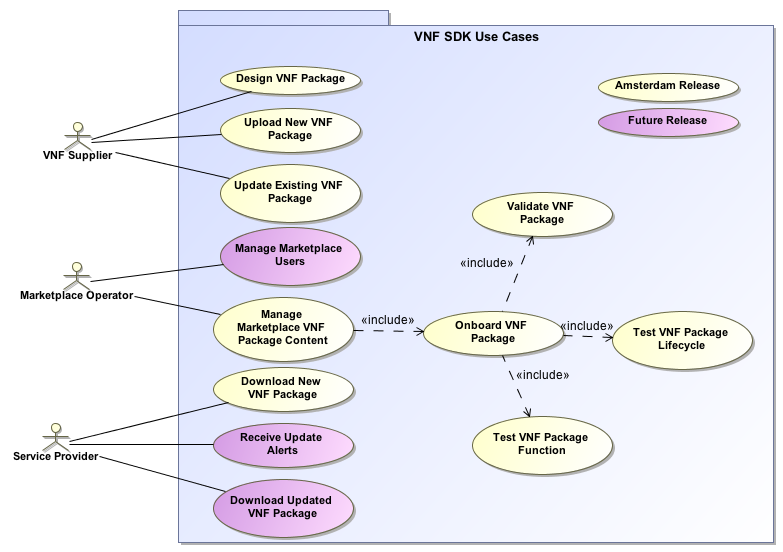
USE CASE DIAGRAM
Use cases define how different users interact with a system under design. Each use case represents an action that may be performed by a user (defined in UML as an Actor with a user persona).
Use Case Functional Definitions
...
Use Case Title
...
Title of the Use Case
...
Actors (and System Components)
...
The list of Actors and System Components that participate in the Use Case
...
Description
...
Short overview of the Use Case
...
Points of Contact
...
Authors and maintainers of the Use Case.
Use Case Lead, Key Use Case members and code contributors.
...
Preconditions
...
A list of conditions that are assumed to be true before the Use Case is invoked
Includes description of Information Consumed
...
Triggers / Begins when
...
Describes the trigger for beginning the Use Case
...
Steps / Flows (success)
...
Describes the sequence of steps and interactions that occur during the Use Case (may include: description, data exchanges, functionality, state changes)
Interaction diagrams may be included or referenced
...
Post-conditions
...
The expected results of the execution of the Use Case
Includes description of Information Produced
...
Alternate / Exception Paths
...
Description of any exceptions or special process that could occur during Use Case
...
Related Use Cases
...
List of the Use Cases referenced by this Use Case
...
Assumptions
...
Describes any assumptions that are made for this use case
...
Tools / References / Artifacts
...
List of any tools or reference material associated with this Use Case as well as any JIRA trace-ability.
List of any associated diagrams or modelling artifacts associated with the Use Case
TESTING
Current Status
Testing Blockers
- High visibility bugs
- Other issues for testing that should be seen at a summary level
- Where possible, always include JIRA links
End to End flow to be Tested
**This should be a summary level Sequence diagram done in Gliffy**
| Gliffy Diagram | ||||||
|---|---|---|---|---|---|---|
|
Test Cases and Status
...
NOT YET TESTED
...
COMPLETE
...
PARTIALLY COMPLETE
Report
Support for vertical industry scenario A in R8

Enhance UUI:
- Deign and develop tenant management portal in ONAP UUI. Through this portal, operator can create the tenant account for vertical industry tenant and assign the instantiated service instance to the corresponding;
- Design and develop separate management portal for vertical industry outside ONAP UUI. Through this portal, vertical industry can query the info which they are allowed to access.
...
The Use case UUI will first query the external database for the relation (assigned-relation) between vertical industry (Yangmei) tenant and the instantiated network service instance and active xNF instance. Now one instantiated network service instance and active xNF instance have been assigned to Vertical Industry (Yangmei) Tenant. The Use case UUI will then query AAI for the detailed info about 5G-RAN-Network-Service-B, 5G-GNB-CU-002 and 5G-GNB-DU-002.

Step 6. Vertical Industry (Yangshan) maintenance officers access the Separate Management Portal. The Separate Management Portalwill present the info about network service instances and xNF instances which has been assigned to the Vertical Industry (Yangshan) Tenant. Now one network service instance (5G-Network-Service-C) has been assigned to Vertical Industry (Yangshan). And the xNF instance (5G-GNB-003 and 5G-UPF-001) which belongs to the network service instance (5G-Network-Service-C) has also been assigned to Vertical Industry (Yangshan) .
...