| Table of Contents |
|---|
Class Diagram
Based on ONF Core IM (https://3vf60mmveq1g8vzn48q2o71a-wpengine.netdna-ssl.com/wp-content/uploads/2018/01/TR-512_v1.3.1_OnfCoreIm-info.zip).
ONAP R2+ Wan Descriptor Connection IM is designed as below class diagram:

...

- Wan Connection: The Wan Connection is Resource Composite.
- Forwarding Construct: The Forwarding Construct (FC) class models enabled constrained potential for forwarding between interfaces at a particular specific layerProtocol.
- FC Port: Fowarding Construct PointPort. The association of the FC to interfaces is made via FC Ports. The FC Port class models the access to the FC function.
- Node: Node resource, it could be a site or a network element or anything else which can be a host for endPoint or any other nodeForwarding Domain: The Forwarding Domain (FD) class models the topological component that represents a forwarding capability that provides the opportunity to enable forwarding (of specific transport characteristic information at one or more protocol layers) between points.
- FC Route: The routing relationships within FC are described, including routing between sub FC (interdomain links), and links between network elements, and exchange relationship within network elements. SubFc describes the lower level FC. FC objects support a recursive aggregation relationship such that the internal construction of FC can be exposed as multiple lower level FC objects (partitioning). Lower level FC could belong to different domain, which is useful for cross domain FC.
- Link Connection: The exchange relationship between nodes, describing how the interfaces between nodes are linked. The link can depend on the FC of the service layer, such as overlay network depend on underlay network.
- XC: Cross Connection. The exchange relationship within a node describes how the interfaces within the node are linked.
- XC Point: Cross Connection Point. Interfaces involved in exchange in a node or a link.
SDO Concept Mapping:
...
ONF Core Im: ForwardingConstruct (TR-512.DD_OnfCoreIm-DataDictionary.pdf 2.1.1.10 ForwardingConstruct )
...
TMF513_v3.1: Cross-Connect (TMF513_v3.1_070314.pdf 4.1.17 Cross-Connect (XC))
...
- Each instance of an FC Route class models an individual route of an FC. The route of an FC object is represented by a list of FCs at a lower level with the implicit understanding that unmodeled link connections are interleaved between the lower level FCs.
- Link: The Link class models effective adjacency between two or more ForwardingDomains (FD).
- LinkPort: The association of the Link to LTPs is made via LinkPort. The LinkPort class models the access to the Link function.
- LTP: The Logical Termination Point (LTP) class encapsulates the termination and adaptation functions of one or more transport layers represented by instances of LayerProtocol.
ONF CIM reference:
| Class Name | SDO Concept |
|---|---|
| Forwarding Construct | TR-512.2_OnfCoreIm-ForwardingAndTermination.pdf 3.2.3 ForwardingConstruct (FC) |
| FC Port | TR-512.2_OnfCoreIm-ForwardingAndTermination.pdf 3.2.2 FdPort |
| Forwarding Domain | TR-512.2_OnfCoreIm-ForwardingAndTermination.pdf3.2.1 ForwardingDomain (FD) |
| FC Route | TR-512.5_OnfCoreIm-Resilience.pdf 3.2.5 FcRoute |
| Link | |
| LinkPort | TR-512.2_OnfCoreIm-ForwardingAndTermination.pdf3.2.6 LinkPort |
| LTP | TR-512.2_OnfCoreIm-ForwardingAndTermination.pdf 3.1.1 LogicalTerminationPoint (LTP) |
The wan connection application for general scenario is shown as below diagram:

Notice:
XC: Cross-Connect
...
...
4.1.
...
ONF Core Im: ForwardingDomain(TR-512.DD_OnfCoreIm-DataDictionary.pdf 2.1.1.11 ForwardingDomain ) & NetworkElement (TR-512.1_v1.2_OnfCoreIm-Overview.pdf 3.3 NetworkElement)
...
17 Cross-Connect), A Cross-Connect (XC) object shall represent a FC within a Network Element (NE).
LC: Link Connection (T-REC-G[1].805-200003-I!!DOC-E.doc 5.2.2.1 Link connection), A link connection is capable of transferring information transparently across a link. It is delimited by ports and represents the fixed relation between the ends of the link. A link connection represents a pair of adaptation functions and a trail in the server layer network. LC is FC (TR-512.TM_OnfCoreIm-TerminologyMapping.pdf page 7)
The wan descriptor application for general scenario is shown as below diagram:

There is a special resource class not shown in the class diagram above, that is configurationspecification. The classes of Wan Descriptor of w an shown above are abstract, we could use them to describe any wan scenario with specify configuration specification which has the specify parameters for the scenario. For example, we could use overlay vpn configuration specification an FC to describe overlay vpn. All specify configuration specification classes are derived from configuration specification base class which is shown as below diagram:


The specify configuration specification class will be consumed by specify Direct Graph in SDN-C. As we could import configuration specification class in SDC and import DG in SDN-C dynamically, new wan scenario could be taught to ONAP after version release.
Use Case Example
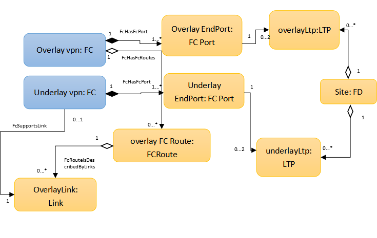
Take the ONAP R1 VoLTE use case as an example. Volte wan contains overlay vpn and underlay vpn, both of them could be described as a FC. And the relationship between overlay vpn and underlay vpn could be described by FCRoute and LinkConnection.


The class diagram of ONAP R1 VoLTE use case shown as below:

Wan descriptor node type definition example: WAN_type_definition.yaml
...
Volte Wan template example: VoLTE_WAN_template.yaml