(Copy this Page in the → ... → select COPY)
Use Case Overview & Description
...
Intent framework is a system that helps to implement and operate networks that can improve network availability and agility. It takes a high-level business goal (intent) as input, converts it to the necessary network configurations and applies the network changes via network automation and/or network orchestration. Continuously monitoring the status of the network under control, the system validates in real time that the intent is being met, and can take corrective actions when desired intent is not met.
It may contain It contains following functional blocks (to be discussed in Honolulu release):
- Intent UI ( Covred in ONAP UUI by
)Jira server ONAP JIRA serverId 425b2b0a-557c-3c0c-b515-579789cceedb key REQ-453 - Intent Management
- Intent Translation
- Intent Decision and Execution Intent Database
- Management:
- Providing NBI for consumers, including intent schema and instance management in a general way
- Intent Translation:
- Translate high-level of abstraction to a more concrete form in order to be validated and processed.
- The system takes a higher-level business goal (what) as input from end users and converts it to the necessary network configuration or orchestration request (how).
- Intent Decision and Execution:
- Decide which, if any, candidate solution shall be executed in response to a request by another managed entity for a set of governance actions.
- Execute one of translated intent solution by sending request to other component, such as SO, CDS, Policy, or external low-level intent system (intent framework).
- Intent Database:
- Store intent schema, intent instance and intent knowledge

Requirement Summary
1. Intent Framework architecture definition
...
*Each Requirement should be tracked by its own User Story in JIRA
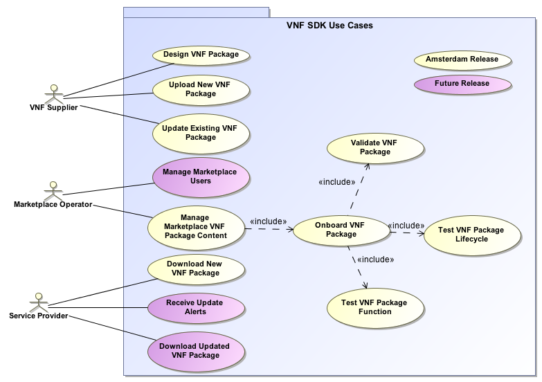
USE CASE DIAGRAM
Use cases define how different users interact with a system under design. Each use case represents an action that may be performed by a user (defined in UML as an Actor with a user persona).

Use Case Functional Definitions
Use Case Title | Title of the Use CaseNetwork Provision | ||
Actors (and System Components) | The list of Actors and System Components that participate in the Use CaseNetwork Operator | ||
Description | Short overview of the Use CaseNetwork Provision | ||
Points of Contact | Authors and maintainers of the Use Case. Use Case Lead, Key Use Case members and code contributors. | ||
Preconditions | A list of conditions that are assumed to be true before the Use Case is invoked Includes description of Information Consumed | ||
Preconditions | Network operator input Intent as : Allocate a network to satisfy the network consumer's intent | ||
Triggers / Begins when | Triggers / Begins when | Describes the trigger for beginning the Use Case||
Steps / Flows (success) | Describes the sequence of steps and interactions that occur during the Use Case (may include: description, data exchanges, functionality, state changes) Interaction diagrams may be included or referenced | ||
Post-conditions | The expected results of the execution of the Use Case Includes description of Information Produced | ||
show as the above figure | |||
Post-conditions | |||
Alternate / Exception Paths | Description of any exceptions or special process that could occur during Use Case | ||
Related Use Cases | List of the Use Cases referenced by this Use Case | ||
Assumptions | Describes any assumptions that are made for this use case | ||
Tools / References / Artifacts | List of any tools or reference material associated with this Use Case as well as any JIRA trace-ability. List of any associated diagrams or modelling artifacts associated with the Use Case |
Supporting materials
Introducton:
TESTING
Current Status
Testing Blockers
- High visibility bugs
- Other issues for testing that should be seen at a summary level
- Where possible, always include JIRA links
End to End flow to be Tested
**This should be a summary level Sequence diagram done in Gliffy**
| Gliffy Diagram | ||||||
|---|---|---|---|---|---|---|
|
Swagger API/ ONAP SO / AAI/ Policy/SDC |
Supporting materials
TEST Report
Test Case:
Network Provision Test Flow
Offered APIs by Intent Framework | |
Implement intent | POST /intents Request Body: {“immediate”: true, “expression”: “xx”} Response”: {“id”:”intent id”} |
Query intent | GET /intents?id={intent id} Response: jsonObject, e.g. {“id”: “intent id”, “state”:”active”, “createTime”:”xx”, ”expression”: ”xx”,”fulfilmentInfo”:”FULFILLED”,”operationList”:”CreateSliceService”} |
Consumed APIs by Intent Framework | |
Create slice service | POST /onap/so/infra/serviceInstantiation/v7/serviceInstances Request Body: jsonObject, {“requestParameters”:{……, “requestInputs”: {“maxNumberUEs”:100, “pLMNIDList”:”xx”, “coverageAreaList”:”xx”}}} |
Service instantiation | POST /onap/so/infra/serviceInstantiation/v7/serviceInstances Request Body: jsonObject, {“requestParameters”: {“userParams”:[{“resources”:{“pnfs”:[“instanceName”:”{nf_instance_name}”]}}]}} |
Test Process:
TBD
Test Cases and Status
| 1 | There should be a test case for each item in the sequence diagram | NOT YET TESTEDCOMPLETE |
| 2 | create additional requirements as needed for each discreet step | COMPLETE |
| 3 | Test cases should cover entire Use Case | PARTIALLY COMPLETE |
...