Name of Use Case:
Enterprise vCPE Use Case
Use Case Authors:
...
Enterprise vCPE Scenario diagram as shown below:

Users and Benefit:
Enterprise customers would benefit from cloud services and automation either on-premises or in the cloud depending on their branch configurations. This will free the enterprise users from the installation, local configuration and administration of LAN/NAT/WAN/VPN networking.
...
ONAP collect link utilization and the actual traffic flows in real-time. when the flow reach the WAN side, the ONAP will conduct the optimal path calculation through configuring MPLS TE tunnels, so as to realize the function of traffic scheduling.
VNF:
Cloud Location | VNFs | Code / Vendor |
Edge | vFW | |
vCPE | ||
vDHCP |
PNF
Cloud Location | Devices | Code / Vendor |
Router | ||
Switch | ||
Server | ||
IPRAN |
ONAP Flows:
- VNFs onboarding

- Service design
- Customer ordering
- Instantiation
- Per service activation
- Cut service
- Instantiation
- Self-service
- Tiered bandwidth
- Bandwidth on Demand(future)
- Change internet access bandwidth
- Software management
- Upgrade service
- Upgrade a specific element (VNF) of the service
- Delete service
- Scaling
- Storage (future)
- Auto-healing
Path Computation Element
Description:
PCE (Path Computation and Element) aims to conduct the path calculation and load balancing for the ONAP network. In the current network, there are multiple vendor controllers along with different path calculation method, and through the PCE, ONAP can analyze data collected from PNFs thus acquiring the whole network topology and flow, and then conduct path calculation uniformly for traffic scheduling and load balancing.
Architecture Alignment:
PCE needs two kinds of information for path calculation and load balancing including network topology and network flow information. In the PCE loop, the module first gets the BGP-LS topology information from the Controller and the network utilization along with network flow information from DCEA/Holmes.PCE will conduct path calculation and load balancing by using those two kinds of information.And then the analysis results are sent to event bus for closed loop automation.
Network Artificial Intelligence
Description:
NAI (Network Artificial Intelligence) component provides data analysis including data detection, prescription and prediction for efficient and intellectualized ONAP network management. And NAI aims to provide traffic prescheduling, policy presetting and resources relocation functions based on the historical data collected from DCAE. Through introducing machine/deep learning algorithms and frameworks, NAI fulfills the fast scheduling automatically and with the well trained NAI system, the accuracy and efficiency will significantly increase compared to the current network management.
Architecture Alignment:
NAI consists of a brain system and a Network Telemetry Analytics (NTA) engine. The NTA engine collected historical data from DCAE then send the data to the brain system to train. With the well trained NAI system, based on the real time data collected from DCAE, the NTA engine generates analysis results to the DCAE and event bus regarding real-time scheduling, prescription and prediction. And the analysis results are the root cause to drive the policy run-time for automation operation.
Network Telemetry Analytics (NTA) engine generates analysis results based on rules and the resources relationships from A&AI.
Current Issues:
- Multiple vendors provide their own controllers without Adapters
- Data and collection filtering
- Fast measure and feedback protocol for requirement of measurement and data collecting
- Language for intelligence network task description
Auto healing flow?
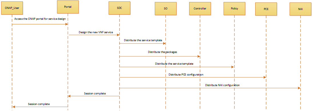
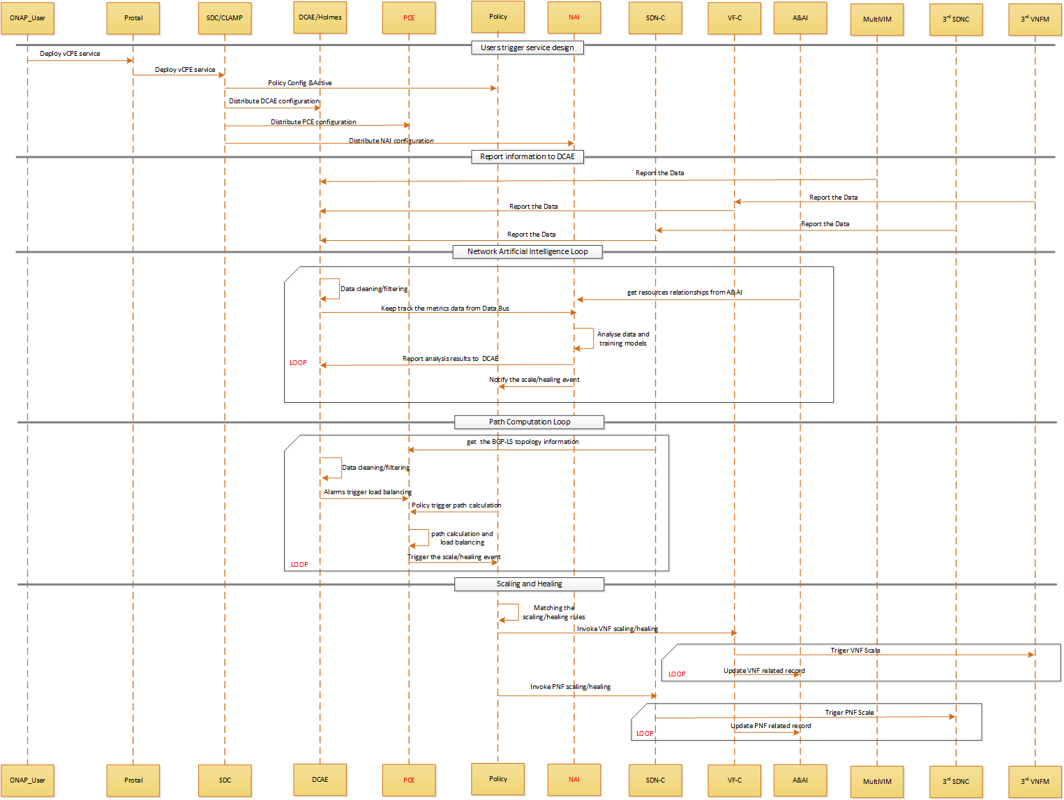
Users trigger service design:
- When ONAP users instantiate the service,they send message to Portal in order to access the ONAP.
- Portal will send message to SDC and CLAMP to deploy vCPE service
- SDC will distribute auto-healing policy rules to policy engine, distribute configuration to NAI and distribute path calculation configuration to PCE as well
- CLAMP portal will talk with DCEA to deploy related analytic application/collector tied to the services
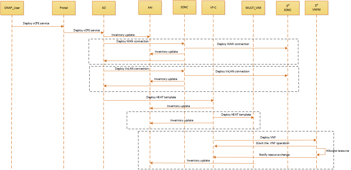
Report information to DCAE:
- Multi-VIM will report FCAPS metrics data to DCAE in real-time or period.
- VF-C will integrate with 3rd VNFM, VF-C will transfer VNF service level FCAPS metrics to DCAE in real-time or period.
- SDNC will integrate with 3rd SDNC, SDNC will transfer PNF service level FCAPS metrics to DCAE in real-time or period.
NAI Loop:
- DCAE will filter and clean the received data,then send related events to data bus.
- NAI can keep track the events published to data bus
- NAI do the data analyses and models training based on the imported configuration and resources relationships from A&AI
- NAI report analysis results to DCAE
- NAI drive the policy run-time for automation operation.
PCE Loop:
- PCE get the BGP-LS topology information from SDNC
- DCAE will filter and clean the received data,then send related events to data bus.PCE can keep track the events published to data bus,and get topology and flow information from DCAE
- Alarms from Holmes will trigger load balancing and policy will trigger path calculation
- PCE do the load balancing and path calculation based on the imported data from DCAE and configuration from SDC
- PCE send the calculation results to the event bus.
Scaling and Healing:
- Policy engine subscribe related topic on event bus. After receiving auto-healing/scaling triggering events, matching the events with exist rules.
- Policy invoke VF-C APIs to do the action of auto-healing/scaling once matching events with scaling/healing rules.
- VF-C update/create related instances information to A&AI inventory according to the changes of resources.
- Policy invoke SDNC APIs to do the action of auto-healing/scaling once matching events with scaling/healing rules.
- SDNC update/create related instances information to A&AI inventory according to the changes of resources.
Control Automation:
- Fault detection and correlation between L2-L3 connectivity services and Internet, E2E Link.
...
- All control automation should be done on VNFs stood up in the operator’s cloud as well as on the CPE
Project Impact:
- Modeling
The enterprise gateway will typically implement a proprietary VIM. Modeling will need to be added to describe how VNFs are to be instantiated, removed, healed (restart, rebuild), how statistics are gathered, how events are received - SDC
Add logic to use the new modeling when designing the service, and then distribute the resulting artifacts - SO
Add logic to understand the new artifacts; orchestrate/manage changes according to it - SDNC
Add logic to issue the proper commands to the CPE to support instantiation, chaining, configuration, healing, etc. - DCAE
Support statistics collection on the CPE and receipt of events as per the new model - APPC/VF-C and DCAE
Support more complex control loops - SO or SDNC
Monitor the CPE to verify the all VNFs and chaining have been executed, and update A&AI. Is more granular information needed? (e.g. on which vServer each VNF is stood up) - A&AI
Support the new data model - Policy
Support new policy related to the connectivity to the CPE
Work Commitment:
Work Item | ONAP Member |
Modeling | |
SDC | |
SO | |
SDNC | |
DCAE | |
APPC/VF-C | |
A&AI | |
Policy |
...