Use Case Authors:
China Mobile, Huawei, VDF
NOTE: More participants are welcome.
Description:
Business Driver:
It is the general demand for big operators such as CMCC and Vodafone to build high-bandwidth, flat and super high-speed OTN (Optical Transport Network) facing with the transition to digital economy and information-based society. They also want to privide a high-speed, flexible and intelligent service for high-value customers, and an instant and flexible VPN service for SMB companies.
The current SOTN has some obvious disadvantages, such as:
- Manual labor is highly needed in service scheduling and resource maintenance which is time-consuming and costly.
- With the high demand for large bandwidth in private line, the expansion to OTN is required. The network needs to be reconstructed under this condition.
- There is no bridge or platform to connect different service providers.
Also, there are urgent demands for:
- Real-time resource update.
- OTN equipment operation and scheduling for different vendors.
- Multi-constrained end-to-end route computation.
- Multi-domain end-to-end service providing.
- Multi-domain network end-to-end survivability.
- Supply SMB companies with VPN service on demand, instantly, flexibly
- Deploy VPN service by overlay mode , untouch carrier network
- “One-click open”and “One-stop”, automatically deploy enterprise VPN service
- Self-service order for client-side CPE, self-delivery client-side CPE
- Provide various value-added service on client-side SD-CPE and cloud side
Considering the above aspects, we plan to make a combination of SOTN and ONAP in virtue of the strong orchestration ability of ONAP, which is called CCVPN(Cross Domain and Cross Layer VPN), to realize a unified management and scheduling of resource and services, and also to deploy services automatically. OTN super controller can be realized as a module of ONAP(SDN-C). In this way, multi-domain cooperation is achieved as well as resource and service automatically providing.
In this use case, our focus is not only restricted to resource, but also services from end to end. Scenarios includes 'SOTN only', SD-VAN and international private line. But at present, 'SOTN only' is at our 1 priority, which is going to be executed in Phase1 in the following.
Function specification priority in the whole plan:
- Priority1: Combine SOTN with ONAP, to manage and orchestrate services automatically.
- Priority2: SD-WAN controller is added in this phase to realize cross Layer VPN services.
- Priority3: Cross-domain E2E Orchestration.
- Priority4: Build up the international private line, to realize the connection between ONAPs.
Action Phases:
- Phase1: SOTN+SD-WAN
- Phase2: ONAPs Connection
Specific sub-use cases are:
- Service onboarding
- Service configuration
- Service termination
- Self service addaption (Bandwidth on demand to be added)
- Auto-scaling based on fault and performance (stretch goal)
- fault detection and auto-healing (stretch goal)
- data correlation and analytics (stretch goal)
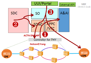
Topology Diagram

Work Flows
Phase1:
Brief description:
After the ONAP brought in, users can forward client service via a unified customer self-service portal. ONAP orchestrator will send out channel built request to SOTN Controller after checking the service request and OTN resource state. Then a private channel is built. Domain controller will finish resource configuration on the basis of ONAP request.
- Topology Notification flow
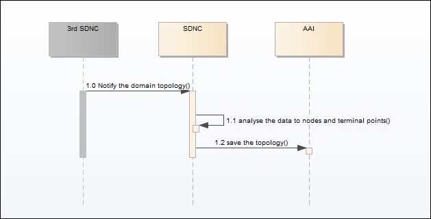
1.0 3rd SDN controller notify the single domain topology to SDNC.
1.1 SDNC analyse the data from 3rd SDN controller. Get the nodes, links, terminal points of the topology.
1.2 SDNC call A&AI to create the nodes, links terminal points to save the topology.
Note: For multi 3rd SDN controllers, there will be several topologies notified. The links across the domain topology should be discovered or created by ONAP. - Service Deploy Flow

- 2.0 The user clicks the button on UUI/Portal to deploy the CCVPN service, UUI/Portal will sent the deploy request to SO.
- 2.1 SO decompose the CCVPN service template distributed by SDC.
- 2.2 SO calls A&AI to create the new service instance in inventory
- 2.3 SO calls SDNC to create CPE configure resource
- 2.4 SDNC calls A&AI to create CPE configure resource instance and attach this resource instance to the service instance.
- 2.5 SO call SDNC to configure CPE
- 2.6 SDNC call 3rd SDN controller to configure CPE.
- 2.7 SO call VFC to create vCPE VNF
- 2.8 VFC create the vCPE VNF instance in A&AI.
- 2.9 SO call VFC to instantiate vCPE VNF
- 2.10 VFC call 3rd VNFM to deploy the vCPE.
- 2.11 SO call SDNC to create vCPE configure resource
- 2.12 SDNC call A&AI to create vCPE configure resource instance and attach this resource instance to the service instance.
- 2.13 SO call SDNC to configure the vCPE
- 2.14 SDNC call the 3rd SDN controller to configure the vCPE.
- 2.15 SO create the VPN network resource instance in A&AI and attach this resource instance to the service instance.
- 2.16 SO query the network access points which CPE and vCPE connects to from the inventory OSS. This access point are the terminal point of the topology in A&AI that notified by 3rd SDN controller(Refer to the flow 1).
- 2.17 SO call OOF to calculate the route between the topology terminal points of CPE and vCPE.
- 2.18 OOF query the whole topology information from A&AI.
- 2.19 OOF calculate the route for the terminal points. And return a VPN list across multi topology.
- 2.20 SO loop the VPNs to call SDNC to instantiate the VPN instance.
- 2.21 SDNC call 3rd SDN controller create vpn over the domain topology.
- 2.22 SDNC add relationship between domain topology and the VPN instance and return the VPN instance to SO.
- 2.23 SO call A&AI to attach the VPN instance to VPN network resource instnace.
3. Service Design Flow
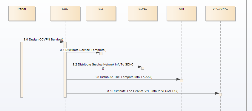
- 3.0 Design the service in SDC portal
- 3.1 SDC distribute the service information to SO
- 3.2 SDC distribute the service network information to SDNC
- 3.3 SDC distribute the service model information to AAI
- 3.4 SDC distribute the service VNF information to VFC/APPC.
Platform Requirements
PNF Onboard (abstract topology)
Deploy Artifacts for physical network
Cross-Operators interwork (MEF etc.)
Tenant management
Project Impact

PHASE1:
SDC – PNF resource onboarding (include: CPE and physical network which can provide MEF EPL service and can be designed as abstract resource)
SO/OOF – service orchestration & homing based on abstract topology(for the physical network)
SDNC - integrated with 3rd controller, New DG for provision to CPE & physical network, sync abstractor topology for the physical network and store it into A&AI
UUI - E2E service provision(need support for tenant & site)
A&AI - DM for PNF, abstract topology of physical network, use travel query tor all resource related to special service
ESR - external controller?OTN controller in phase 1?, external inventory OSS to provide reference between physical location information and CPE or UNI/NNI of physical network, or external link between different physical network domain(stretch goal)
DCAE - collect the event data for MEF EPL service or from PNF.
VF-C/APP-C –VNF deployment & management when need
External APIs - external controller?OTN controller in phase 1?, external inventory OSS to provide reference between physical location information and CPE or UNI/NNI of physical network, or external link between different physical network domain(stretch goal)
- Modeling - the modeling for PNF and abstract topology for physical network
PHASE2+:
- ESR - SD WAN controller & external OSS: inventory/order etc.
- External API - cross operator’s service interwork
- Policy - E2E close-Loop for cross domain service
Priorities (TBD)
PNF:
CPE: customer premises equipment, the equipment located at an end-user's premises, can be configure or managed via CLI or controller.
Physical network: a SDN network that can provide E2E MEF EPL service to ONAP, it can be multi-layer network, an 3rd controller can separate the control plane and the forward plane, and will handle the instantiation and LCM of EPL under the command from ONAP, and provide abstract topology to ONAP to facility the homing calculation.
Location | PNFs | Intended Provider | PNF CSAR |
Site | CPE | Huawei | |
Physical network | OTN network element | Huawei | |
VNF:
VNF: vCPE or similar VNF/APP that need to deploy in site (the enterprise or the Datacenter).
NFVI+VIM: provide infrastructure to run VNF/app.
Location | VNFs | Intended VNF Provider | VNF CSAR |
enterprise | vCPE | Huawei | |
Datacenter | |||
NFVI+VIM:
Utilize vendors NFVI+VIMs in the ONAP platform.
Location | NFVI+VIMs | Intended VNF Provider | Note |
Datacenter | |||
Work Commitment
< identify who is committing to work on this use case and on which part>
Work Item | ONAP Member Committed to work on CCVPN |
Modeling | CMCC, VDF, Huawei |
SDC | Huawei |
SO | Huawei |
OOF | Huawei |
SDN-C | CMCC, Huawei |
UUI | CMCC, Huawei |
DCAE | Huawei |
VF-C | Huawei |
A&AI | Huawei |
External API | Huawei |
Attachments: