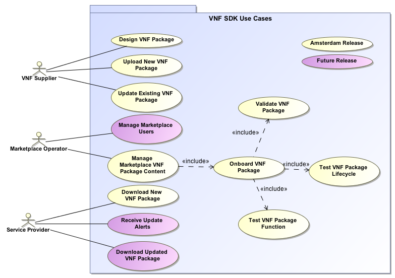
Use Case Diagram
Use cases define how different users interact with a system under design. Each use case represents an action that may be performed by a user (defined in UML as an Actor with a user persona).
Use Case Functional Definitions (one table for each Use Case)
| Section | Description |
|---|---|
Use Case Title | Title of the Use Case |
Actors (and System Components) | The list of Actors and System Components that participate in the Use Case |
Description | Short overview of the Use Case |
Points of Contact | Authors and maintainers of the Use Case |
Preconditions | A list of conditions that are assumed to be true before the Use Case is invoked Includes description of Information Consumed |
Triggers / Begins when | Describes the trigger for beginning the Use Case |
Steps / Flows (success) | Describes the sequence of steps and interactions that occur during the Use Case (may include: description, data exchanges, functionality, state changes) Interaction diagrams may be included or referenced |
Post-conditions | The expected results of the execution of the Use Case Includes description of Information Produced |
Alternate / Exception Paths | Description of any exceptions or special process that could occur during Use Case |
Related Use Cases | List of the Use Cases referenced by this Use Case |
Assumptions | Describes any assumptions that are made for this use case |
Tools / References / Artifacts | List of any tools or reference material associated with this Use Case as well as any JIRA trace-ability. List of any associated diagrams or modelling artifacts associated with the Use Case |