Note: Some edits to the text and flow diagrams are still expected in the next few days. These edits are the result of meetings and decision taken regarding the use case in the past 2-3 weeks. Most of the work-impacting modifications have already been communicated and reviewed with the relevant projects; those that haven't yet are expected to have minor impact, and will be reviewed during the week of Aug 21st.
Name of Use Case:
Residential Broadband vCPE
Use Case Authors:
Amdocs, AT&T, Intel, Orange, Wind River
Description:
Technical Report 317 (TR-317) from the Broadband Forum specifies a "Network Enhanced Residential Gateway" (NERG) that can be used by service providers (SP) to deploy residential broadband services including High Speed Internet access, IPTV and VoIP services. A new device type named BRG (Bridged Residential Gateway) is defined, as well as a functionality split between what it would run and what a virtual function instantiated in the SP's cloud, called vG, will run. This functionality split allows for the introduction of new services not possible with the existing whole-physical residential gateway. It also saves operational cost with less changes / truck roll in and to the customer residence would be needed.
Key for this use case is:
- ONAP will be used to instantiate, configure and manage the vCPE service as a cloud service that may be collocated with other subscriber services such as vSTB, cloud DVR and VoD-streaming vCDN.
- SDN is used to configure the connectivity with the first mile network, the IP subscriber management and service edge networking. Potentially in the future, dynamic service chaining to value-add services (e.g. security, parental control, home automation IoT).
The full details for this this new residential gateway can be found in the BBF report. For ONAP Release 1 (Dec 2017) a subset of the full functionality of TR-317 will be included in the VNFs implementing the vCPE use case; but the ONAP behavior for the use case will be mostly what will be expected from ONAP in a production network.

The diagram above depicts the R1 vCPE use case (with the exception of the home networks on the left which will not be part of the tested use case). The IP addresses and VLAN numbers are for illustration purposes, the actual values may be different in the final set up. In particular, IPv6 addresses may be used in place of IPv4 10.x.x.x in the above.
Users and Benefit:
- Residential users benefit from subscriber specific cloud services and automation that does not need truck roll installation, local configuration and management of LAN/NAT/WAN/VPN networking.
- Authenticated subscribers may access similar broadband services outside the home residence using other wireline or wireless access networks.
- SPs benefit from a more flexible platform to evolve residential broadband services that do not depend on the lifecycles of provided home devices (e.g. STB, WiFi access router, modem etc…)
Scope
To be added
R1 Use Case Flows
Basic flow for establishment of the LSL (Logical Subscriber Link):
- At stand-up time SDNC configures BRG Emulator with the address of vG_MUX for tunneling. SDNC knows this address because SDNC assigned it prior to vG_MUX stand up.
- BRG Emulator comes up and issues a DHCP Discover request for its WAP i/f
- The request contains option 125 (BBF) with sub-option NERG Device Type (24) with string "BRG"
- For the demo - the request will include option 82 as if entered by an AN
- vBNG intercepts the DHCP request, stores it, and issues a Radius Access-Request with the DHCP request options to vAAA
- vAAA sends the Access-Accept back to vBNG
- Upon receiving the accept vBNG restores the DHCP request and relays it to vDHCP
- vDHCP sends a DHCP Offer with the BRG WAN IP
- BRG Emulator sends a DHCP rquest with its WAN IP address
- vBNG snoops the request and relays it to vDHCP
- vDHCP sends a DHCP Ack to BRG
- BRG Emulator creates a new VxLAN tunnel interface over it WAN interface using its WAN IP as the local address and the configured vG_MUX IP as the remote address.
The newly created tunnel i/f will be used for all communications between BRG Emulator and its pair vG. Below is the frame format of packets sent inside this tunnel:
VXLAN Packet Format

Fields description going from right to left in the figure above:
- Original L2 Frame consists of the whole packet that should eventually arrive in vG, starting from the original MAC header.
- VXLAN Header: This is an 8-byte (64-bit) field that includes the following fields:
- Flags: 8 bits in length, where the 5th bit (I flag) is set to 1 to indicate a valid VNI. The remaining 7 bits (R bits) are reserved fields and are set to zero
- Reserved fields must all be set to 0 when sending and ignored when receiving.
- VNI: 24-bit value that provides a unique identifier for the individual VXLAN segment.
- Outer UDP Header: The source port in the outer UDP header is dynamically assigned by the originating VTEP (BRG Emulator or vG_MUX) and the destination port is the well-known UDP port 4789.
- Outer IP Header: The outer IP header has a source IP address of the source VTEP (when sent by BRG Emulator - its WAN IP) . The outer destination IP address is the IP address of the destination VTEP (when sent by BRG Emulator - the vG_MUX IP).
- Outer MAC Header: The outer Ethernet header has a source MAC address of the VTEP (when sent by BRG Emulator - its MAC addr on its WAN i/f). The destination MAC address is the MAC address of the routing next-hop to reach the destination VTEP (when sent by BRG Emulator - the MAC addr of vBNG on its interface facing BRG Emulator)
The role of vG_MUX is to terminate VXLAN tunnels (typically utilizing public IP addresses) and relay packet to/from local vGs. In the vCPE use case VLAN IDs are used to distinguish between different vGs connecting to vG_MUX. To this end vG_MUX maintains a XC tabel of the following format: <Remote VTEP IP, VNI VNI, VNI VLAN ID>. vG_MUX uses this table as follows:
BRG Emulator → vG direction:
- When a packet arrives, vG_MUX looks up in its XC table an entry in which the arriving 2-tupple: <src_VTEP, VNI> matches < BRG_WAN_IP_ADDRESS, VNI>
- If found, vG_MUX replaces the <dst_VTEP> filed in the packet with the <vG_IP_ADDRESS> field in the found entry, the <src_VTEP> with its own "right" ip address, leaves all other fields intact, and sends the packet to the vG.
- If not found ( normally should not happen), the packet is discarded, and a counter counting such events is incremented. In future releases we may consider issuing an SNMP trap in such situations.
vG → BRG Emulator direction:
- When a packet arrives, vG_MUX looks up an entry in which the arriving 2-tupple: <VMI, src_VTEP> matches <VNI, vG_IP_ADDRESS>.
- If found, vG_MUX replaces the <dst_VTEP> filed in the packet with the <BRG_WAN_IP_ADDRESS> field in the found entry, the <src_VTEP> with its own "left" ip address, leaves all other fields intact, and sends the packet to the BRG.
- If not found ( normally should not happen), the packet is discarded, and a counter counting such events is incremented. In future releases we may consider issuing an SNMP trap in such situations.
The first transaction that uses the VxLAN tunnel is the BRG Emulator's request to get its own IP address for its LAN interface, as follows:
- BRG Emulator sends a DHCP Discover packet for its LAN i/f to its pair vG (inside the VxLAN tunnel).
- vG_MUX gets the packet and tries to find the corresponding entry in its XC table. Since this is the very first packet of this kind such entry is not found; vG_MUX creates a corresponding entry (see above) and forwards the packet to vG
- vG sends a DHCP Offer with an address its DHCP server assigns to BRG Emulator's LAN i/f (from 192.168.1.0/24)
- vG_MUX encapsulates the packet properly, and sends it over the corresponding VxLAN tunnel.
- BRG Emulator sends a DHCP request with the offered address to vG (inside the tunnel)
- vG_MUX forwards the packet to vG
- vG sends a DHCP ACK
- vG_MUX encapsulates the packet properly, and sends it over the corresponding VxLAN tunnel.
Once BRG Emulator gets the ACK it is ready to start serving the home network.

Network Function:
Location | VNF | Code / Vendor | Comments |
DC1 | BRG Emulator Goal: Release 1 | VPP + modification by Intel | VPP based software used as the BRG emulator for the use case |
Aspiration goal:
Monitoring of metrics and alarms of the BRG and automated action. Example policy based on monitoring:
- Automatic reboot of the BRG because of high load (CPU).
Virtual Network Function / VNF:
Location | VNFs | Code / Vendor | Comments |
DC1 | vBNG Goal: Release 1 | Open Source:
| BNG: Broadband Network Gateway Includes suscriber session management, traffic aggregation and routing, and policy / QoS. |
vG_MUX Goal: Release 1 | Open Source:
| ||
vG, including DHCP Goal: Release 1 | Open Source:
DHCP Server source: TBD | Provides basic routing capabilities and service selection for residential services. | |
vAAA Goal: Release 1 |
| Access authentication and authorization. | |
vDHCP Goal: Release 1 |
| Instance 1: BRG WAN IP address assignment Instance 2: vG WAN IP address assignment | |
vDNS Goal: Release 1 |
| Domain name resolution |
NFVI+VIM:
Location | NFVI+VIMs | Code / Vendor | NFVI+VIM requirement |
| DC1 | OpenStack |
| NFV Infrastructure and Virtual Infrastructure Management system that is compatible with ONAP Release 1. |
ONAP Flows:
Modeling vCPE Residential Broadband Services
The vCPE use case consists of several VNFs and networks that can be thought of as Resources which fall into two categories:
1. Infrastructure - These Resources are deployed prior to any customer request for an instance of vCPE Residential Broadband service. These VNFs and networks are assumed to be up and running and ready when a customer order is received. Some of this infrastructure (e.g,. the vGMUX VNF) may be dedicated to supporting vCPE Residential Broadband service instances, and others (e.g., the vDHCP VNF) may provide shared functionality across many service types. We will refer to the latter as "Core Infrastructure".
2. Customer - These Resources are dedicated to a particular customer service instance, and hence are instantiated on a per vCPE Residential Broadband service customer request basis.
Because the Infrastructure Resources support many vCPE Residential Broadband service instances, and because the Core Infrastructure Resources provide support for perhaps many service types, it is appropriate to think of these as collectively providing various underlying "Services" to a higher order customer Service. We will model these Resources accordingly as being comprised of Infrastructure Services which support the vCPE Residential Broadband Customer Service.
Infrastructure Services Modeling
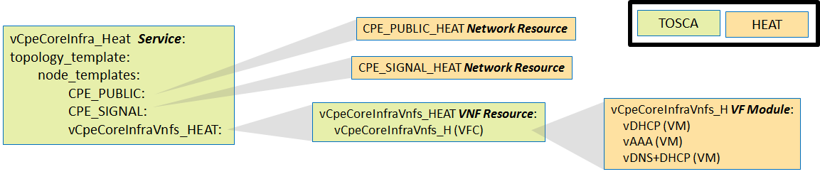
In the "real world", the vDHCP, vAAA, and vDNS+DHCP functions would each be deployed separate of each other. However, because as "Core Infrastructure" they provide only a generic supporting function for this use case and are not integral to the purposes of this use" case, it is less critical that we model these functions as we would find them in the "real world". Hence we will take this opportunity to demonstrate a more complex VNF by modeling this functionality as a single VNF comprised of three VMs, packaged into a single HEAT template.
We will model a vCpeCoreInfra_Heat Service that is comprised of this complex VNF as well as two networks:, the "CPE_PUBLIC" and the "CPE_SIGNAL" networks. Thus, a request into ONAP to create a new instance of vCpeCoreInfra_Heat Service in a particular cloud region will result in an instance of the CPE_PUBLIC network and the CPE_SIGNAL networks being instantiated in that cloud region using the CPE_PUBLIC_HEAT and CPE_SIGNAL_HEAT HEAT templates respectively, as well as an instance of the single VNF being instantiated in that cloud region using the single VNF HEAT template.
From a modeling perspective we will leverage the concept of "VF Module" (analogous to the concept of ETSI Virtual Deployment Unit, or VDU) to capture the "unit of deployment" within a multi-VM VNF. Thus, we will model the this HEAT template as a single vCpeCoreInfraVnfs_H VF Module.
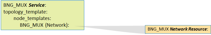
In the "real world" the network between the BNG and the vGMUX would likely be a shared network that multiple BNGs could use to communicate to multiple vGMUXs, and hence it is reasonable to model that network as not being part of the same Service (and Service instance) as the BNG or the vGMUX. Hence we will model it as a separate Service which can be instantiated in a given cloud region independently of, but of course prior to, the VNF instantiation.
The network between the BRG and the BNG is specific to a particular BNG instance, and thus it is reasonable to model it as part of the same Service (and Service instance) as the BNG.

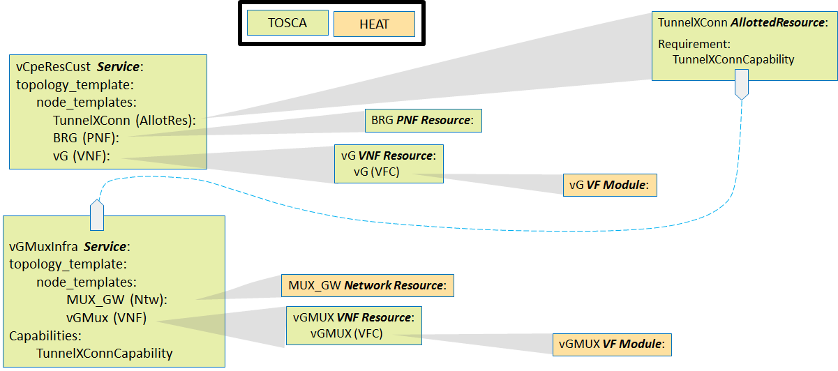
In the "real world", each instance of the Customer Service will be comprised of:
- A BRG, which will be a physical device (PNF) dedicated to the customer's service instance.
- A vG, which is a virtual network function that is dedicated to the customer's service instance.
- A "slice" of functionality of the vGMUX, which provides a "cross connect" function between the BRG and vG. We use the term "slide" informally to convey the sense that something (capacity) is consumed and dedicated (configuration record) in the vGMUX for this customer's service instance. The way in which SDC models a "slice" of functionality of a VNF is through the "Allotted Resource" construct, because what is being consumed by the customer's service instance is an "allotment" of capacity and configuration from the underlying vGMUX. We will refer to this as the TunnelXConn Allotted Resource.
Because in this sense the vGMUX is providing a "service" an allotment of which is being consumed, we consider the TunnelXConn Allotted Resource to be taken from the vGMUX's Infrastructure Service, vGMuxInfra.
Though in the "real world" the BRG will be a physical device, for purposes of this use case we will emulate such a physical device via a VNF, the vBRG_EMU VNF. We will instantiate this VNF separately from the Customer's service instance, and model it as a separate service: BRG_EMU Service. Upon instantiation of a BRG_EMU service instance with its vBRG_EMU VNF, that VNF will begin acting like its "real world" PNF counterpart.

As a Release 1 ONAP "stretch goal", we will also attempt to demonstrate how a standalone general TOSCA Orchestrator can be incorporated into SO to provide the "cloud resource orchestration" functionality without relying on HEAT orchestration to provide this functionality. As such we will model the "vCpeCoreInfra" Service in a manner that does not leverage HEAT templates, but rather as pure TOSCA.

Note: All detailed flows (with diagrams) are for R1. Flows planned for subsequent releases are tagged as "aspiration" and are only mentioned, details will be added later.
Onboarding of vCPE VNFs

Service Instantiation Flow
Generic Run Time Flows
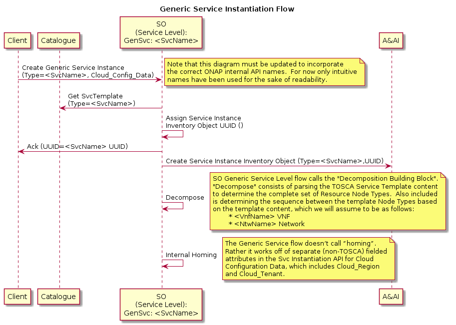
For "simple" Services which include only simple networks and VNFs (e.g., with no multi-data instances that map to different VF Modules), there exists an SO “Generic Service” flow (“top level flow”) that spawns Resource Level VNF and/or Network sub-flows that are themselves "Generic". By "Generic" we mean that the SO flows were built with no particular Service, VNF, or Network in mind, but are rather implemented in such a way to support many different Service, VNF, and Network types. The SDC model drives which particular sub-flows to spawn and of which type, as well as driving the specific behavior of the Service level and Resource level flows.
For such "simple" Services, the SDNC functionality is also “generic” such that only modeling and configuration is needed to drive SDNC behavior for a specific VNF type. For example, the SDNC generic VNF flow can automatically assign IP Addresses from a pool that has been pre-loaded into SDNC. E.g., pre-load 25 vG instances with their assignments pre-populated. SDNC keeps track of which instances have/have not been assigned.
It is expected that these SO and SDNC assets will be leveraged for most of the Services and Resources needed for the vCPE use case, though some custom flows will also be needed as per the following table:
Service | Service Level Flow | Resource | Resource Level Flow | SDNC Northbound API | SDNC DG |
|---|---|---|---|---|---|
vCpeCoreInfra_X | Generic Service | vCpeCoreInfraVnfs_X (VNF) | Generic VNF | GENERIC-RESOURCE | Generic DG |
“ | CPE_PUBLIC (Network) | Generic Ntw | GENERIC-RESOURCE | Generic DG | |
“ | CPE_SIGNAL (Network) | Generic Ntw | GENERIC-RESOURCE | Generic DG | |
vGMuxInfra | Generic Service | vGMUX (VNF) | Generic VNF | GENERIC-RESOURCE | Generic DG |
“ | “ | MUX_GW (Network) | Generic Ntw | GENERIC-RESOURCE | Generic DG |
vBngInfra | Generic Service | vBNG (VNF) | Generic VNF | GENERIC-RESOURCE | Generic DG |
“ | BRG_BNG (Network) | Generic Ntw | GENERIC-RESOURCE | Generic DG | |
BNG_MUX | Generic Service | BNG_MUX (Network) | Generic Ntw | GENERIC-RESOURCE | Generic DG |
BRG_EMU | Generic Service | BRG_EMU (VNF) | Generic VNF | GENERIC-RESOURCE | Custom Process (Event Handling) |
vCpeResCust | Custom [New] | TunnelXConn (AR) | Custom [New] | GENERIC-RESOURCE | Custom DG [New] |
“ | “ | vG (VNF) | Generic VNF | GENERIC-RESOURCE | Generic DG |
“ | “ | BRG (PNF) | Custom [New] | GENERIC-RESOURCE | Custom DG [New] |
The run time functionality of these generic flows is as follows:
Generic Service Instantiation Flow
Generic Resource Level flow for Networks

Generic Resource Level Flow for VNFs
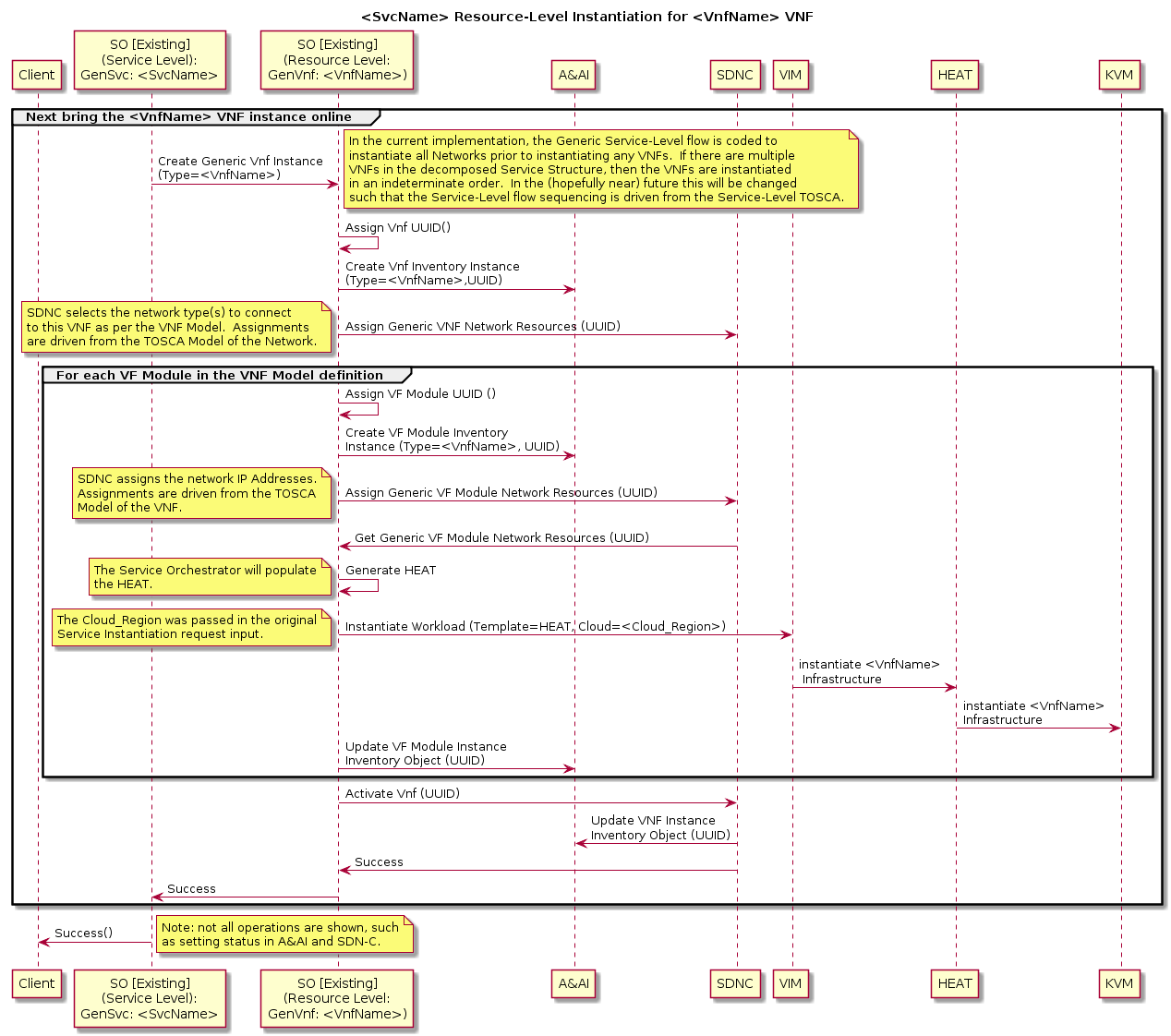
Use Case Order of Operations
The assumed order of operations for the run time use case experience is as follows:
- Via VID, user will request ONAP to create an instance of the vCpeCoreInfra_X Service (HEAT or TOSCA based)
- Via VID, user will request ONAP to create an instance of the BNG_MUX Service.
- Via Robot, request ONAP to create an instance of the vGMuxInfra Service.
- Via VID, user will request ONAP to create an instance of the vBngInfra Service.
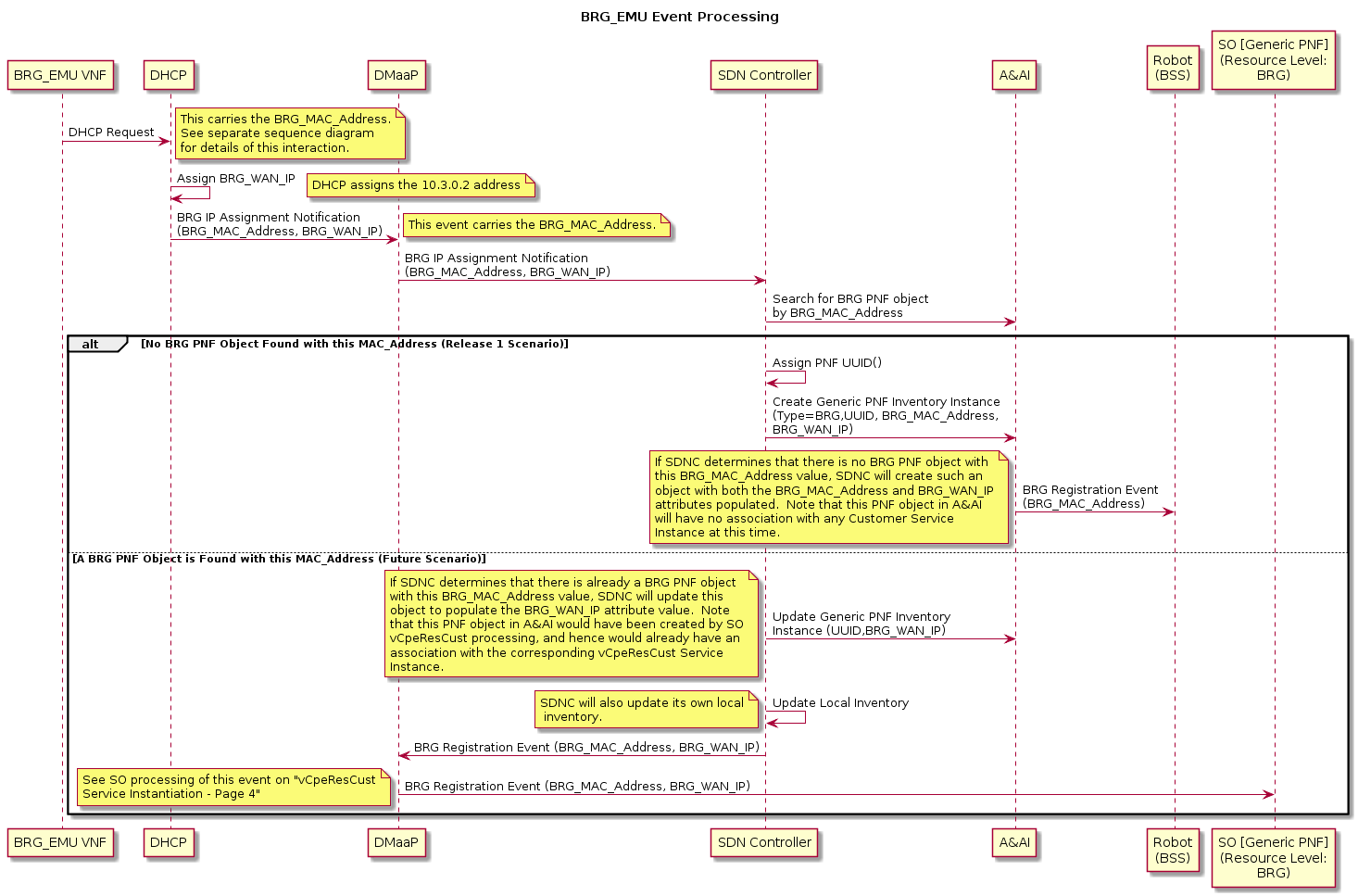
- Via Robot, request ONAP to create an instance of the BRG emulator, the BRG_EMU Service. The associated BRG-emulating VNF will come online and start behaving like a BRG, among other things initiating a sequence of events that will result in the BRG being inventoried in A&AI, which in turn results in A&AI generating another event that is intercepted by Robot.
- Robot, now acting as a BSS emulator, upon receipt of the A&AI event, will request ONAP to create an instance of the vCpeResCust Service.
The diagram below shows more detail of step 5 in the above sequence. Note that only the "No BRG PNF Object" alternative flow is in scope for Release 1. (I.e., in Release 1 the assumption is that the BRG PNF (emulated) will always be "plugged in" prior to the "customer service request" being released to ONAP.)
For more details on the instantiation flows described at a high level above, see the attached PDF.
Other Flows
- Aspiration goal: Cut service
- Aspiration goal: Per service activation ( connectivity to Internet, IMS VoIP, IPTV)
- Aspiration goal: Wholesale access (future)
- Self-service
- Aspiration goal: Tiered bandwidth
- Aspiration goal: Bandwidth on Demand
- Aspiration goal: Change internet access bandwidth
- Software management
- Aspiration goal: Upgrade service
- Aspiration goal: Upgrade a specific element (VNF) of the service
- Aspiration goal: Delete service
- Scaling
- Aspiration goal: Storage (future)
- Aspiration goal: Cut service
- Auto-healing
- Automatic reboot/restart
- Aspiration goal: Rebuild
- Aspiration goal: Migrate/evacuate to different CO Re-architected as DC (future)
- Aspiration goal: Reconnect over an alternative path?

Project Impact:
- Modeling
To be discussed - SDC
Add logic to use the new modeling when designing the service, and then distribute the resulting artifacts. - CLAMP
Framework for policy design and distribution - SO
Add logic to understand the new artifacts; orchestrate/manage changes according to it. - SDNC
Add logic to create the chaining, configuration, healing, etc. - DCAE
Support statistics collection and receipt of events as per the new model; monitor connectivity and livelihood of the BRG_Emulator. - APPC, VF-C, and DCAE
Support more complex control loops. - A&AI
Support the new data model. - Policy
Support new policy related to the service + the connectivity to the BRG_Emulator. - VNF SDK
Support the ONAP VNF guidelines (blend from ECOMP and OPEN-O) - Integration
Integrate, produce test cases, run the tests, verify the use case with the selected VNFs
- Modeling
Work Commitment:
| Work Item | ONAP Member |
| Modeling | Amdocs, AT&T |
| SDC | Amdocs, AT&T |
| SO | AT&T |
| SDNC | Amdocs, AT&T |
| DCAE | AT&T |
| APPC | Amdocs, AT&T |
| A&AI | Amdocs |
| Policy | AT&T |
| Multi-VIM | Wind River |
VPP Based VNFs BRG_Emulator, VBNG, vG_MUX, vG | Intel |
| Integration | Amdocs, Integration Team |
| Use Case Subcommittee | Amdocs, AT&T, Intel, Orange, Wind River, more ? Deliverables: Service definition, service detailed requirements, ONAP flow diagrams, service(s) model(s) |
Note: Work commitment items indicate which ONAP Members have expressed interest and commitment to working on individual items. More than one ONAP Member is welcomed to provide support and work on each of the items.
Design and Test Cases:
Related Tutorials:
Meetings:
- Jun 28, 2017 Meeting: Use Case Walk Through
- Yoav walked through the use case flows so that people from different project can understand the details and subsequently identify impact/requirements/issues related to their respective projects. Jun 30, 2017 Meeting: Closed Loop Control
- Yoav presented the flow on automatic reboot/restart.
- One question was whether we want to restart VNF or VM. The answer is to restart VM.
- Data collection vG_MUX --> DCAE: What needs to be worked out is the VES version and payload to be supported by vG_MUX. DCAE would like to have sample data from the VNF. Yoav will bring these requirements to Danny Lin.
- Events DCAE --> Policy: The content of the events should be well defined.
- Control Policy --> APPC: The detailed interface definition needs to be worked out.
- Mapping from VNF ID to VM ID: The current flow shows that APPC will query AAI to perform the mapping. Further discussion is needed to decide where to do it: APPC or Policy.Jun 30, 2017 Meeting: Design Time
- Yoav presented the VNF onboarding process
- VxLAN is preferred for the tunnels between BRG and vG MUX. Tunnels from different home networks will share the same VNI but are differentiated using the BRG IP addresses.
- Ron Shacham explained that CLAMP will create a blutprint template that will be used to instantiate a DCAE instance for the use case. CLAMP is not responsible for the development of the DCAE analytics program.
- It is determined that the infrastructure service and per customer service should be created individually.
- Yang Xu from Integration pointed out that VNF address assignment/management (including OAM IP and port IP) needs further discussions. Yoav will update the use case architecture diagram to include OAM IP addresses.
- It is realized that service design is complicated and needs more discussions. Yoav will follow up on these topic and schedule meetings.
- Micheal Lando mentioned that a new version of SDC is being set up in AT&T. Daniel will check whether the community can get access to it.Jul 6, 2017 Meeting: Design Time
- Recorded meeting is here.
- Brian Freeman explained that APPC should query AAI to get the VM ID and then perform VM restart.
- Currently that APPC polls to get the state after sending out restart command. There were discussions on using callback to get state change. Brian suggested that it be put in R2.
- Discussed the mapping between VxLAN tunnel and the VLAN between vG_MUX and vG1.Jul 9: closed loop diagram updated reflecting the discussion
- Jul 12: Important Questions
Discussed a the list of important questions. Refer this page: Use Case Related Important Questions and Answers - Jul 13: Service Model
- Gil Bullard presented the first version of service model. He will update his slides based on the discussions and then post them here
- Jul 18: Service Model Driven Orchestration
Gil Bullard presented the attached slides. Recorded meeting is here.
- July 19:
Kang suggested that each project review the service model and work flows presented by Gil on 7/18 to confirm the required features.
Went through the questions on this page to get answers or point of contact. Kang will follow up by email. - July 21:
Ron Shacham presented CLAMP design for vCPE. Please watch the recorded meeting. The slides are here. - Aug 1:
vCPE service model and workflow discussion. Recorded meeting. - Aug 3:
vCPE service model, workflow, and network. Recorded meetings: session1, session2. (server is too busy to accept video upload, will try again later)