1. Architecture
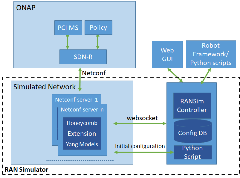
The high-level architecture of the RAN simulator and its interface to ONAP is shown below.
2. Netconf server
- Honeycomb simulator shall be used to simulate the Netconf server. Suitable extensions will be made for it to communicate with the RANSim Controller.
- Each netconf server will run as standalone process or in a Docker container
- The netconf servers will be spawned by RANSim Controller based on the topology specified.
- Python scripts and client will seed the initial configuration for each Node.
- Each netconf server can send a mount request to SDN-R when it is spawned.
- ran-neighbor-list update notification will be sent by netconf server to SDN-R based on the trigger from RANSim Controller.
- The netconf server will be able to accept phy-cell-id update trigger from SDN-R and forward same to RANSim Controller.
- Maximum number of cells connected to a netconf server is configurable (currently configured as 16).
3. RANSim Controller
- This is a Springboot based micro-service
- RAN topology of ~2000 cells to be simulated is defined into a Config DB.
- RAN Simulator spawns the netconf servers based on this topology
- Exposes following rest APIs for GUI to:
- Retrieve the current topology
- Update phy-cell-id of a cell to simulate collision or confusion
- Update neighbor list to simulate collision or confusion (in the table view)
- Receive the new phy-cell-id set by SDN-R (after PCI optimization, or otherwise)
- Start/Stop the network simulation
- MariaDB will be used as the Config DB to store the topology
- Robot scripts will drive the test sequences
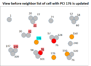
- Web GUI will show the current topology, phy-cell-id collision/confusions (using different color codes), ran-neighbor-list.
- Basic pictorial representation will be provided, improvements will be a stretch goal.
RAN-Sim GUI
4.1. Assumptions
- For initial setup, an input file containing foll. info shall be used
- Cell Id
- PNF name (though this has really no relevance to the GUI)
- Cell position = {0,1,2,3} 0=>no sectors, 1-3 denotes sectors
- PCI value
- (x,y) = mapping to a co-ordinate on the canvas from (lat,long)
- Neighbor list (ordered list of (cell id, PCI))
- Canvas view and ‘on-click’ views possible
- Editable contents: neighbor list (in graphical view), PCI value (in graphical view)
- Maximum 3 cells in a single location
- All cells are assumed to be of same size, i.e., path loss, etc. are not considered.
- Option provided for user to pause before seeing the changed PCI values.
- Only 1 iteration of PCI/neighbor list change will be performed.
4.2. Illustration of GUI
4.2.1. Canvas view when a neighbor list of a cell is updated


4.2.2. Canvas view when a neighbor list of a second cell is updated (OOF is not yet triggered)


4.2.3. Details of a particular cell (on click view)


5. Simulation setup and sample test sequences
5.1. Setup
The topology of the RAN to be simulated along with the details of the cells to be provided as input. This can be done in 2 ways:
- RANSim controller obtains number of clusters, cluster size, PCI range available via GUI and sets up the network. This is currently being implemented.
- A config file is provided with the network topology. However, this should contain details such as cellID, neighbor list, (x,y) co-ordinates (could be lat-long) of each cell also (for the display).
In either case, OOF shall get offline inputs of the network topology and neighbor list details to set up its own DB.
5.2. Test sequences
- A neighbor list change or PCI change is triggered via GUI. As a result, all impacted cells are identified and netconf notifications sent to ONAP (SDN-R). This triggers PCI optimization, and results are then fed back to RANSim. RANSim then displays the changed configuration.
- Different color codes are used for active cells, cells experiencing collision, confusion, etc.
Note: When a second change is triggered, any effect of the first change is also transmitted (i.e., neighbor list changes due to PCI optimization implementation) to ONAP.
3 Comments
Arash Hekmat
As we discussed on the PCI PoC call, in terms of the packaging of this RAN Simulator and making it available to the community, the method below can be used.
Example:
Netbox is an IP resolution service used by SDN-C. The docker image is on the docker hub here: https://hub.docker.com/r/ninech/netbox
It is then packaged by a Helm chart in OOM here: https://gerrit.onap.org/r/gitweb?p=oom.git;a=tree;f=kubernetes/contrib/charts/netbox;hb=refs/heads/master
Brian Freeman
I think we treat the IPAM as a contribution and refer to the external docker as appropriate. Just need to make sure that if its really ONAP it should be in LF nexus. If it has a life of its own outside of ONAP and Linux Foundation then docker hub it fine.
Arash Hekmat
Agree.