Name of Use Case:
Enterprise vCPE Use Case
Use Case Authors:
China Telecom, China Mobile, Huawei, ZTE, ARM, Accenture
Presentation Materials:
8.28 usecase subcommittee meeting.pptx
E-vcpe presentation material in F2F meeting - 9.25?
Description:
This use case is mainly used for the Enterprise Service Provider (SP) to provide the Enterprise2DC service to the tenants both efficiently and safely by deploying enterprise-based vCPE. Enterprise users could receive high-quality and cheap cloud service based on the operator’s BSS Portal and ONAP. And in here, ONAP is used to instantiate and operate the required vCPE in the access network as a cloud service.
For the application scenarios of E-vCPE use case, it supports site-to-site, site-to-DC and site-to-Internet services to the customers. It not only provides the solution of ThinCPE and vCPE in the edge-DC but also CPE solution as an alternative choice for enterprise customer. The solution of vCPE in the edge-DC is an actual deployment scheme which can provide more value-added service in DC and make it easy for access control.
In this case, ONAP will present its function to instantiate, configure and manage both the overlay connection between site-to-site/DC/Internet and VNFs . There are three alternative ways to set up overlay connection, including VxLAN, IPSec and MPLS. It is a stretch goal to fulfill traffic scheduling in WAN network by means of path calculation and load balancing.
Enterprise vCPE Scenario diagram as shown below:

Users and Benefit:
Enterprise customers would benefit from cloud services and automation either on-premises or in the cloud depending on their branch configurations. This will free the enterprise users from the installation, local configuration and administration of LAN/NAT/WAN/VPN networking.
SPs would benefit from a more flexible platform to provide more kinds of virtual services. To implement the configuration remotely will help SPs reduce complexity of the service deployment and cut down the OPEX. Besides, ONAP can manage a large number of business orders from BSS or user self-service systems, which can improve service efficiency. The order management services include three core functions, such as order resolution and calibration, order execution, and order reporting.
The centralized traffic scheduling and optimization of backbone network is the embodiment of SDN concept in backbone network, it will help operators enhance the management ability of operation and maintenance and improve the efficiency of resource utilization.
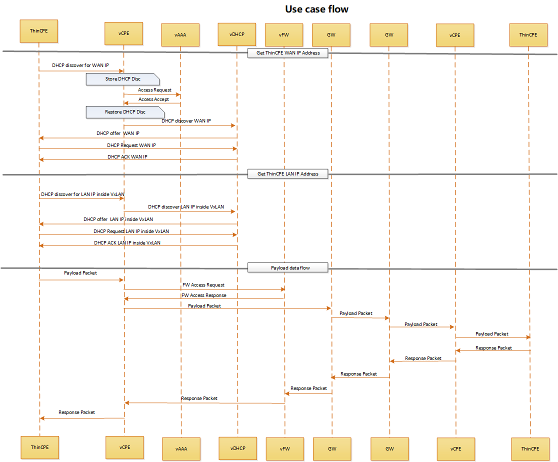
Use Case Flows
1.site2DC

ThinCPE's request to get its own IP address for its WAN interface
· ThinCPE send DHCP Discovery message to vCPE for WAN IP
· vCPE store the DHCP Discovery request and then send access request to vAAA
· vAAA reply access accept message,vCPE restore the DHCP Discovery request
· ThinCPE send DHCP Discovery message to vCPE for WAN IP
· vCPE send DHCP Discovery message to vDHCP for WAN IP
· vDHCP sends a DHCP Offer with an address its DHCP server assigns to ThinCPE's WAN IP
· ThinCPE sends a DHCP Request with the offered address to vDHCP
· vDHCP sends a DHCP ACK
ThinCPE's request to get its own IP address for its LAN interface inside the VxLAN tunnel
· ThinCPE send DHCP Discovery message to vCPE for LAN IP
· vCPE send DHCP Discovery message to vDHCP for LAN IP
· vDHCP sends a DHCP Offer with an address its DHCP server assigns to ThinCPE's LAN IP
· ThinCPE sends a DHCP Request with the offered address to vDHCP
· vDHCP sends a DHCP ACK
Once ThinCPE has acquired its own IP address for its LAN and WAN interfaces, it could have access to DC.
ONAP collect link utilization and the actual traffic flows in real-time. when the flow reach the WAN side, the ONAP will conduct the optimal path calculation through configuring MPLS TE tunnels, so as to realize the function of traffic scheduling.
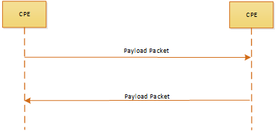
2.
site2site—choice1 (vCPE)
site2site—choice2 (CPE)
VNF:
Cloud Location | VNFs | Code / Vendor |
Edge | vFW | |
vCPE | ||
vDHCP |
PNF
Cloud Location | Devices | Code / Vendor |
Router | ||
Switch | ||
Server | ||
IPRAN |
ONAP Flows:
- VNFs onboarding

- Service design
- Customer ordering
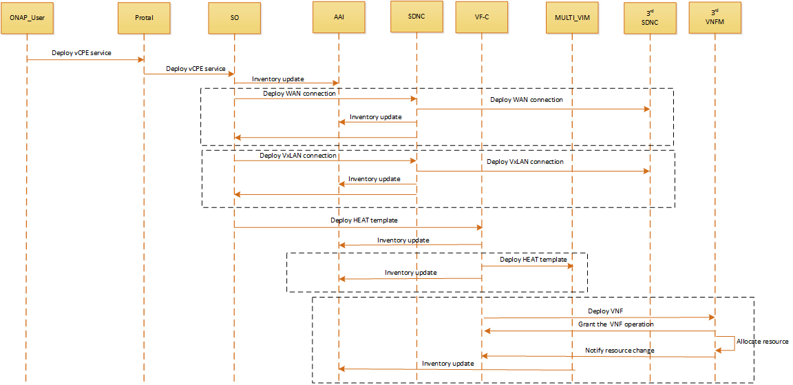
- Instantiation
- Per service activation
- Cut service
- Instantiation
- Self-service
- Tiered bandwidth
- Bandwidth on Demand(future)
- Change internet access bandwidth
- Software management
- Upgrade service
- Upgrade a specific element (VNF) of the service
- Delete service
- Scaling
- Storage (future)
- Auto-healing
Path Computation Element
Description:
PCE (Path Computation and Element) aims to conduct the path calculation and load balancing for the ONAP network. In the current network, there are multiple vendor controllers along with different path calculation method, and through the PCE, ONAP can analyze data collected from PNFs thus acquiring the whole network topology and flow, and then conduct path calculation uniformly for traffic scheduling and load balancing.
Architecture Alignment:
PCE needs two kinds of information for path calculation and load balancing including network topology and network flow information. In the PCE loop, the module first gets the BGP-LS topology information from the Controller and the network utilization along with network flow information from DCEA/Holmes.PCE will conduct path calculation and load balancing by using those two kinds of information.And then the analysis results are sent to event bus for closed loop automation.
Network Artificial Intelligence
Description:
NAI (Network Artificial Intelligence) component provides data analysis including data detection, prescription and prediction for efficient and intellectualized ONAP network management. And NAI aims to provide traffic prescheduling, policy presetting and resources relocation functions based on the historical data collected from DCAE. Through introducing machine/deep learning algorithms and frameworks, NAI fulfills the fast scheduling automatically and with the well trained NAI system, the accuracy and efficiency will significantly increase compared to the current network management.
Architecture Alignment:
NAI consists of a brain system and a Network Telemetry Analytics (NTA) engine. The NTA engine collected historical data from DCAE then send the data to the brain system to train. With the well trained NAI system, based on the real time data collected from DCAE, the NTA engine generates analysis results to the DCAE and event bus regarding real-time scheduling, prescription and prediction. And the analysis results are the root cause to drive the policy run-time for automation operation.
Network Telemetry Analytics (NTA) engine generates analysis results based on rules and the resources relationships from A&AI.
Current Issues:
- Multiple vendors provide their own controllers without Adapters
- Data and collection filtering
- Fast measure and feedback protocol for requirement of measurement and data collecting
- Language for intelligence network task description
Auto healing flow?
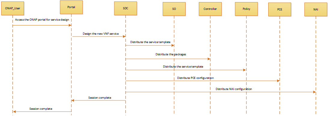
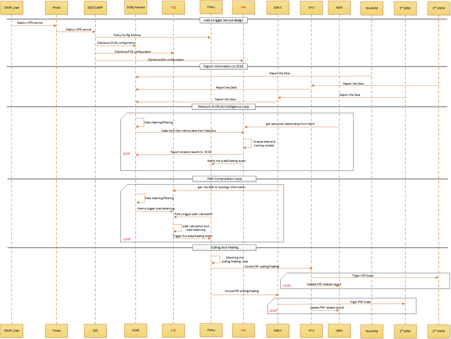
Users trigger service design:
- When ONAP users instantiate the service,they send message to Portal in order to access the ONAP.
- Portal will send message to SDC and CLAMP to deploy vCPE service
- SDC will distribute auto-healing policy rules to policy engine, distribute configuration to NAI and distribute path calculation configuration to PCE as well
- CLAMP portal will talk with DCEA to deploy related analytic application/collector tied to the services
Report information to DCAE:
- Multi-VIM will report FCAPS metrics data to DCAE in real-time or period.
- VF-C will integrate with 3rd VNFM, VF-C will transfer VNF service level FCAPS metrics to DCAE in real-time or period.
- SDNC will integrate with 3rd SDNC, SDNC will transfer PNF service level FCAPS metrics to DCAE in real-time or period.
NAI Loop:
- DCAE will filter and clean the received data,then send related events to data bus.
- NAI can keep track the events published to data bus
- NAI do the data analyses and models training based on the imported configuration and resources relationships from A&AI
- NAI report analysis results to DCAE
- NAI drive the policy run-time for automation operation.
PCE Loop:
- PCE get the BGP-LS topology information from SDNC
- DCAE will filter and clean the received data,then send related events to data bus.PCE can keep track the events published to data bus,and get topology and flow information from DCAE
- Alarms from Holmes will trigger load balancing and policy will trigger path calculation
- PCE do the load balancing and path calculation based on the imported data from DCAE and configuration from SDC
- PCE send the calculation results to the event bus.
Scaling and Healing:
- Policy engine subscribe related topic on event bus. After receiving auto-healing/scaling triggering events, matching the events with exist rules.
- Policy invoke VF-C APIs to do the action of auto-healing/scaling once matching events with scaling/healing rules.
- VF-C update/create related instances information to A&AI inventory according to the changes of resources.
- Policy invoke SDNC APIs to do the action of auto-healing/scaling once matching events with scaling/healing rules.
- SDNC update/create related instances information to A&AI inventory according to the changes of resources.
Control Automation:
- Fault detection and correlation between L2-L3 connectivity services and Internet, E2E Link.
- Manage localized enterprise services by automatically performing the health check of the access connectivity, virtual switching/routing and auditing of service-related configurations
- Deliver high availability service requirements for emergency communications and surveillance services
- All control automation should be done on VNFs stood up in the operator’s cloud as well as on the CPE
Functional Platform Requirement and Priorities:
Functional Platform Requirements | Priority | Basic/stretch goal Default basic goal | Related components |
Connectivity configuration | 1 | SDNC | |
Traffic scheduling | 3 | PCE, NAI, DCAE, SDNC, A&AI | |
Overlay selection | 1 | Portal, SO, SDNC | |
Order management | 2 | Common Service, A&AI, SO | |
VNF onboarding | 1 | ||
Service Design | 1 | ||
Service Composition | 1 | ||
Network Provisioning | 1 | ||
Deployment automation | 1 | ||
Termination automation | 1 | ||
Policy driven/optimal VNF placement | 3 | ||
Performance monitoring and analysis | 2 | ||
Resource dedication | 3 | ||
Control Loops | 2 | ||
Capacity based scaling | 3 | ||
Triggered Healthcheck | 2 | ||
Health monitoring and analysis | 2 | ||
Data collection | 2 | ||
Data Analysis | 2 | ||
Policy based healing | 3 | ||
Policy based scaling | 2 | ||
Configuration audit | 3 | ||
Multi Cloud Support | 2 | ||
Framework for integration with OSS/BSS | 3 | ||
Framework for integration with vendor provided VNFM(if needed) | 1 | ||
Framework for integration with external controller | 1 |
Project Impact:
1.portal
Support E-vCPE case lifecycle management actions, monitor service instances status, display FCAPS metrics data in real time, select Overlay connection ways(IpSec/VxLan).
2. SDC
Design vCPE network service;
Design policies (eg. Auto-healing policy, design alarm correlation rules );
Design work flow used by SO/VF-C/SDN-C;
Design E2E service…
3. DCAE
Support statistics collection on the CPE and receipt of events as per the new model in real time ,for example network utilization along with network flow information, jitter etc.
4. Policy
Support to define and execute auto-healing policy rules;
Handling the notifications related to VNF and PNF alarms/events ;
5. A&AI
Inventory model for E-vCPE;
Add support to PNFs
Infrastructure resources ;
Topological information, E2E service lifecycle management, decompose E2E service and talk with VF-C/SDN-C to instantiate services respectively in NFV/SDN domain;
6. SO:
E-vcpe service workflow execution (E2E service lifecycle management, decompose E2E service and talk with VF-C/SDN-C to instantiate services respectively in NFV/SDN domain)
7. SDN-C
Network connection service lifecycle management;
Integrate with 3rd party SDN Controllers to setup MPLS VPN for underlay;
Integrate with 3rd party SDN Controllers to setup overlay connection;
Support current node status information collection and so on.
8. APP-C/VF-C
Network service lifecycle management;
VNFs in E-vCPE usecase lifecycle management;
Integrate with EMS to collect FCAPS metrics data of VNF level and do Application configuration;
Integrate with Multi-VIM to do virtual resource management;
9. PCE
Integrate with controller to get the BGP-LS topology
Integrate with DCEA/Holmes to get network flow information
Conduct path calculation and load balancing
10. NAI
Data detection, prescription and prediction;
Provide traffic pre-scheduling, policy pre-setting and resources
relocation functions;
11. Order Management
Take orders from BSS for management: order storage, decomposition, execution status management, completion report, etc
Work Commitment:
Work Item | ONAP Member |
Modeling | |
SDC | |
SO | |
SDNC | |
DCAE | |
APPC/VF-C | |
A&AI | |
Policy |
10 Comments
Sujing Zhang
1?Suggest that the flow chart be added to illustrate the usecase interaction process?
2?Suggest that the connection channel of ThinCPE to edge DC is proposed to increase the access mode of IP metropolitan area network?
Danny Zhou
The behaviors (e.g. handle DHCP request, authentication process by interfacing with vAAA and vDHCP) of vCPE described in the sequence diagram above is very similar to the vBNG in the residential vCPE use case at Use Case: Residential Broadband vCPE (Approved). Specifically, if I do a 1:1 mapping like below:
1) ThingCPE ↔ BRG_Emulator
2) vCPE ↔ BNG
3) vDHCP + vAAA ↔ vDHCP + vAAA
Is it possible to merge this enterprise vCPE use case to residential vCPE use case? Say, reusing those common features for VNFs, but adding PNFs mentioned above as a advanced feature for R2.
ramki krishnan
Some questions
1) Is the TIC-Core a Enterprise or Cloud Data Center since it depicts a website with a OS?
2) There is an MPLS path and IPSEC path between the edge and core DCs? Are we looking at a SD-WAN solution?
Thanks,
Ramki
luman wang
Hi, Ramkik
Thanks for your comments. According to your questions, here are the points I want to express:
1. The TIC-Core is a Clould DC and this use case is mainly used to provide service for Enterprise2DC. Actually, there will be various applications in DC, for example, vFW?vLB etc.
2. Yes, the Enterprise vCPE expands some enhanced network features in ONAP including providing three alternative ways (Vxlan, IPSec and MPLS) for network connection between edge and core DCs. And the SD-WAN solution is an important component of our use case.
Thanks,
Luman
Evgeniy Zhukov
ONAP is able for number of features to support. Some list of features can be combined together for specific Use Cases for Business purposes. SD-WAN and E-vCPE Use Cases have overlapped list of feauters. Both of them about overlay connectivity between CPE and Cloud. And their difference in a way, how to create such connectivity:
In Contrast with Mobile world, where Roumers getting service, Fixed world use Overlay VPN to provide service in 3rd party networks.
It is up to Customer to choose which of this two products will meet his business requirement, mostly in terms of Location and QoS.
On top of basic functionality become available new advanced features. For example, both Use Cases is open for SFC Implementation. SD-WAN can dynamycaly create direct overlay connections between Branch Offices, building Mesh Topology, while E-vCPE always is a Star Topology.
So, Ramki, thanks for this good question about vCPE and SD-WAN differences.
And Luman, I agree with your point about this two Use Cases have a lot of common features, which need to be specified in terms of ONAP somehow.
luman wang
Hi Evgenity,
Thanks for your comment.
1. The Enterprise-vCPE use case we proposed supports not only the underlay connection but also overlay connection. The MPLS VPN is based on operators’ network, but the VxLAN/IPsec connection could be based on underlay / overlay either way.
2. The Enterprise-vCPE use case is focused on the flexible requirement of customers. And also reflects the inclusivity and scalability requirements of ONAP. Our technical proposal can be applied partially or completely to other Network Providers, thus the customer site can establish connections over Internet crossing Network Providers.
3. Given underlay / overlay connections, we provide site-to-site, site-to-DC and site-to-internet service to the customer?in the case of site-to-site, our proposal may run through TIC-edge or not, the TIC-edge could provide multiple service, but without TIC-edge, direct site-to-site connection under SDNC controller would cover the SD-WAN use case.
Thank you again for your response about the questions, I am looking forward to make further discussion with regarding use case scenario and technical proposal details.
mark gibson
Hello
I really like this use case and the detail set out in the use case focussing as much on the distribution of the artefacts as the fulfilment flow itself.
Michael O'Brien
OPNFV references
https://wiki.opnfv.org/display/AUTO/Use+Case+proposal%3A+Enterprise+vCPE
Arash Hekmat
Hello
I was wondering if you guys could tell me how the ThinCPE boxes are configured for this Enterprise vCPE use case? I mean which ONAP module actually sends the configuration to the ThinCPE box? Is SDN-C doing this? And where does the ThinCPE configuration come from? And also how is the configuration sent to these ThinCPE boxes? Is it NETCONF? Is it REST? or is it just CLI?
Thank you
Evguenia (Jane) Freider
Hi, is this use case being implemented in R2 (Beijing) release? I don't see an official approval clause here...Could you please summarize?